Form designer: Smart busbar visual component
The component is intended for drawing electric circuits. It can contain child components of the user, as well as its own "special" components - "SmartConnection" (connection) and "SmartNode" (node), which are not available from the palette - it is dynamically created by the component as a result of drawing a circuit.
The component is empty right after adding it to the form from the palette. The user is supposed to draw a diagram, filling it with the necessary nodes and linking them with connections. And after that, he can configure each node and connection separately.
Circuit draw
To enter the drawing mode (of nodes and connections), you may either:
- double-click on an empty area of the component - a "node" (a circle, a new SmartNode component) is created in this place and the component enters drawing mode.
- double-click on an existing node (SmartNode component) and the component enters drawing mode.
In circuit drawing mode, the component offers to draw a "connection" from the host node, to one of the four directions, depending on the position of the mouse cursor. A single click on an empty space within the component creates a new node (SmartNode) and connects the old and new nodes (by the SmartConnection component). Drawing continues from the new node.
To exit the drawing mode, click once on an existing node.
If, after drawing mode, a node is not connected to another node, then that node will be deleted. Also, after drawing mode, you can select and move nodes and delete nodes and connections.
Principle of operation
The circuit consists of nodes and connections. The connection can either be a simple connection or of a "breaker" type, while the breaker may have its own internal state "Open"/"Closed"/"Unknown". All possible circuit states, colors and priority of each state are defined on the SmartBusbar component. Nodes can dictate their state (for example, the "Has power" state) and propagate this state to a neighboring nodes via connections. The circuit elements are colored according to the highest priority state declared by the nodes. It is very easy to add dynamics - for example, some node will change its "node".Power soure state depending on one datasource' tag, and breaker will change its "breaker".State state depending on another tag, - all the circuit will be calculated and painted automatically, no matter how complex it is, and no manual calculations is required.
SmartBusbar component
The component has the following properties:
- "bus".
Bus width- Bus width (in pixels). This property controls width of all child components of SmartConnection and SmartNode types. It makes sense to increase the thickness before editing for the convenience of editing, and low it down after editing to make it more nice. - "bus"
- "bus".
Change color duration- The duration of the bus color change animation, in ms. - "bus"."breaker".
Close duration- The duration of the breaker closing animation (angle breaker type), in ms. - "bus"."breaker".
Open duration- The duration of the breaker opening animation (angle breaker type), in ms. - "bus".
Power states- number of bus states. Changing this setting dynamically adds (or removes) subgroups, describing bus state, to the Property Inspector:
Each bus state is described by a group of properties: - "bus"."state N".
Priority- Numerical identifier of the state priority, the lower the priority number, the higher the priority. - "bus"."state N".
Name- The name of the state. - "bus"."state N".
Color 1- Color1 of the state. - "bus"."state N".
Color 2- Color2 of the state. If color1 and color2 are different, then there will be a gradient fill out of these colors.
In addition, the component has a dedicated "error state", - a special state with a customizable colors, it is applied when it is impossible to calculate the state of the bus.
By default, the component defines 3 states (which can be overridden):
- "Blackout" - No electricity, black color.
- "Has power" - Electricity is available but not OK, red color.
- "Power OK" - Electricity is available and OK, green color.
- "Power unknown" - Erroneous state, gray color.
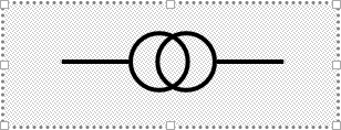
SmartNode component
On the circuit it looks like a translucent circle
- "node".
Size factor- Node size factor. The default is 1 - node size equals to the bus width. If you put 2 - the node will be 2 times thicker than the bus width. - "node".
Power source state- You can select one of the bus states that this node propagates to neighbour elements. By default, the first state "Blackout" is selected. - "node".
Node color- Either "follow bus" - the node (circle) will be painted with the computed bus state color, or "self source" - the node will be painted with the state color that this node dictates itself.
SmartNode has position properties and properties related to determine behaviour when size of the parent component changes - "horizontal stick", "vertical stick" - if there is a goal to make scaling for the SmartBusbar component, then for each node of this component you also need to set these properties to the "scale" value.
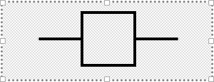
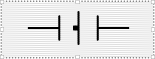
SmartConnection component
Connects two nodes. Properties:
- "connection".
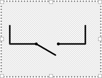
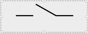
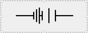
Type- Either "Connection" (by default), or "Breaker". - "connection".
Size factor- element scaling factor, default is 1. - "connection".
Sub Type- subtype, for breaker:- "Anglebreaker"
- "Auto breaker"
- "Disconnector"
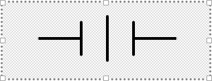
- "Separator"
- "Grounding knife"
- "Short circuiter"
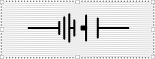
- "VT"
- "Anglebreaker"
- "connection"."breaker".
State- "unknown" - Unknown state.
- "closed" - Breaker is closed.
- "intermediate" - Breaker is in an intermediate position (for some subtypes of switches).
- "open" - Breaker is open.
- "error" - Error condition (red slash is drawn)
- "connection"."breaker".
Reverse- Allows you to change the binding node (when breaker is open) of the angle breaker subtype. - "connection"."breaker".
Angle close- Degree of inclination of the closed angle breaker. 0 degrees by default. - "connection"."breaker".
Angle open- Degree of inclination of the open angle breaker. 30 degrees by default.
State transfer from one node of this connection to another is carried out only if the connection type is Connection, or Breaker with "closed" state.